Recently I bought the GROVE starter bundle pictured below
But the cables (and the LCD) went missing. When I complained about the missing items I was replied with the information that they will arrive in a few days. The cables arrived yesterday indeed, but I'm still waiting for the LCD.
For testing purposes I connected the expansion shield (the big board with many white connectors on it) to the Netduino, and I started testing the modules. Here is what I found out:
1. The majority modules components are connect almost directly to the microcontroller, there is no I2C converter. I was expecting a different somehow since the jigsaw puzzles apparently were meant to be connected to a bus.
2. Led module:
D1 drives the Red led.
D2 drives the Green led.
2. Buzzer module
It is an ON/OFF buzzer controlled by D1 alone. You can't control the frequency and if you send a square wave, you'll get a strange flickering sound.
Arduino lessons
Friday, December 24, 2010
Playing with the GROVE System using Netduino
Labels:
buzzer,
eletronick brick,
grove,
led,
seeedstudio
Wednesday, December 15, 2010
Using the Codec-Adaptative Wireless Relay with the 315Mhz Wireless Car Key Fob
I recently bought the Codec-Adaptative Wireless Relay
And the 315Mhz Wireless Car Key Fob
2. You can clear all memorized signals by pressing the programming button until the led goes off.
3. You can add program new signals by pressing the programming button and then sending the signal.
The key fob emits different signals for each button and button combination. So button 1 sends a different signal than button 2, and both signals are different from pressing button 1 and 2 together. A single key fob can emit up to 16 different signals, but due to hardware limitations you can only use 15 of these, by pressing button combinations.
Two key fobs are unlikely to emit the same signals, as the main component (HS1527) datasheet states that it uses a 20 bit random salt for its signals. That means that you can have up to 1M (1,048,576) different key fobs.
And the 315Mhz Wireless Car Key Fob
Luckly they work together. And quite well. As soon as you get yours, all you need to learn how to use them is to plug the 12 V DC power source to the Relay.
You can't program the Key Fob, but you have to program the Relay.
1. Choose the operation mode for the Relay:
A. Latch – Connect pin 1 and 2 – all memorized signals toggles the relay state.
B. Interlock – Connect pin 2 and 3 – some signals activates the relay, while other signals deactivates it.
C. Non-latch – Empty – the relay remains in a normal state except when it is receiving a expected signal. As soon as the signal reception is interrupted, the relay returns to its normal state.
2. You can clear all memorized signals by pressing the programming button until the led goes off.
3. You can add program new signals by pressing the programming button and then sending the signal.
The key fob emits different signals for each button and button combination. So button 1 sends a different signal than button 2, and both signals are different from pressing button 1 and 2 together. A single key fob can emit up to 16 different signals, but due to hardware limitations you can only use 15 of these, by pressing button combinations.
Two key fobs are unlikely to emit the same signals, as the main component (HS1527) datasheet states that it uses a 20 bit random salt for its signals. That means that you can have up to 1M (1,048,576) different key fobs.
Sunday, November 14, 2010
How to use electret microphones?
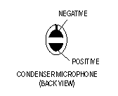
Electret microphones have built-in amplifier transistors. So to get it's output you will need a pull-up resitor:
You should pay attention to which pin is connected to the case, because this is the negative pin:
Tuesday, November 2, 2010
I lost connection to my XBee module, what now?
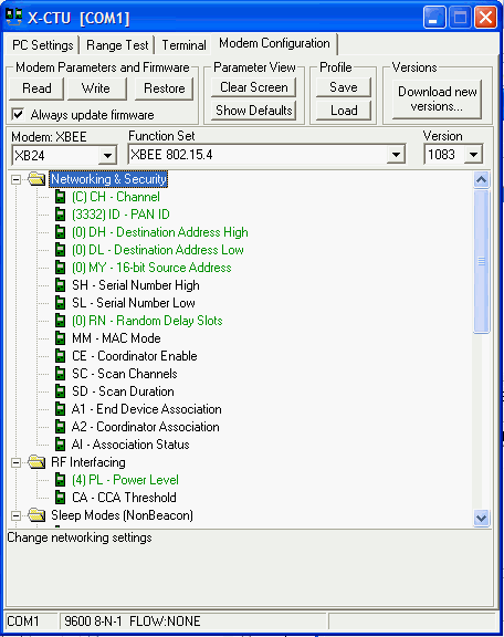
When you program your XBee with different profiles such as API (instead of AT), your XBee will lose the ability to communicate via UART. Those modes are meant to be used with a RS232 dev board.
To get back in touch with your module you'll have to follow these steps:
1. Take the module out of the interface board.
2. Connect the interface board to the computer.
3. Open X-CTU
4. Go to "Modem Configuration"
5. Put a check in the "Always update firmware" box
6. Select proper modem from drop down menu,
7. Select proper function set and firmware version
from drop down menus.
8. Click on the "Write" button. After a few seconds of
trying to read the modem, you will get an Info box
that says Action Needed. At this point, CAREFULLY
insert the module into the interface board.
9. You may get the info box again a short while after,
just use the reset button on the interface board.
Saturday, October 30, 2010
How to write 10-bit ADC values to the 8-bit serial with Arduino?
The following code:
So what you have to do is to fix this behavior
int sensorValue = analogRead(A0);
Serial.println(sensorValue, DEC);
Outputs (text):
0
1023
for the same input values the following code:
int sensorValue = analogRead(A0);
Serial.write(sensorValue);
Outputs (bytes)
00 63The 0 got through, but the 1023 resulted in 63. This happens because:
- ADC resolution is 10-bit
- Thus the maximum value is 1023 (0x3FF)
- Serial.Write writes the more valuable 8 bits
- Serial.Write considers the ADC output as a 12 bit variable
- 63 (0x3F) are the 8 more valuable bits in this variable
So what you have to do is to fix this behavior
int upperByte = (sensorValue & 0x300) >> 8;
int lowerByte = sensorValue & 0xFF;
Serial.write(lowerByte);
Serial.write(upperByte);
Then you will get right aligned data:
00 00 FF 03With
int upperByte = (sensorValue & 0x3FC) >> 2;
int lowerByte = (sensorValue & 0x3) << 6;
You get left aligned data for unsigned integers
00 00 C0 FFWith
int upperByte = (sensorValue & 0x3F8) >> 3;
int lowerByte = (sensorValue & 0x7) << 5;
You get left aligned data for signed integers
00 00 E0 7F
Thursday, October 28, 2010
How to use a XBee module?

- Download the configurator GUI: Digi X-CTU download
- Install and open X-CTU
- Select the Com Port.
- Open the "Modem Configuration" tab.
- Click on Read.
- You'll have to set one of your XBee modems as a "COORDINATOR AT" in the dropdown list "Function Set".
- Click on the "Write" button
- Leave the rest of the modems as "ROUTER/END DEVICE AT"
- Now your Coordinator will transmit to the rest of the modules
Tuesday, October 26, 2010
What happens if I only get the positive part of the signal?
I bought a Microphone and Amplifier eletronic brick, which came with the LM386 AmpOp.
The problem was that the Vin (pin 2) of this IC was grounded, thus the output renders only the positive part of the signal.
Instead of this:
I had then 2 solutions:
1. Either I could modify the hardware to input into the Vin a Vcc/2 voltage.
2. Or I could deal with the distortion via software.
To see if I could restore the signal I analysed its spectrum of the distorted signal:
And I had to restore it to look like this:
For such a simple signal a simple low pass filter would do. But I realized that it would be impossible for more complex signals.
Here is the Matlab/Octave code that I used to generate the plots above:
Fs = 44100;
time = linspace(0, 1, Fs + 1);
sine = sin(2 * pi * 440 * time);
plot(time, sine);
figure;
player = audioplayer(sine, 44100);
play(player);
positiveOnly = (sine + abs(sine)) / 2;
plot(time, positiveOnly);
figure;
player = audioplayer(positiveOnly, Fs);
play(player);
sineSpectre = fft(sine);
plot(time, sineSpectre);
figure;
positiveOnlySpectre = fft(positiveOnly);
plot(time, positiveOnlySpectre);
Subscribe to:
Posts (Atom)


